About AI Consulting Deep-Tech Sovereign AI
AI Solutions
Team Contact

AI for Technical Drawings

Engineering drawing review interface showing annotated technical schematics

Fleet-Wide Intelligence, Engineer-Scale Control

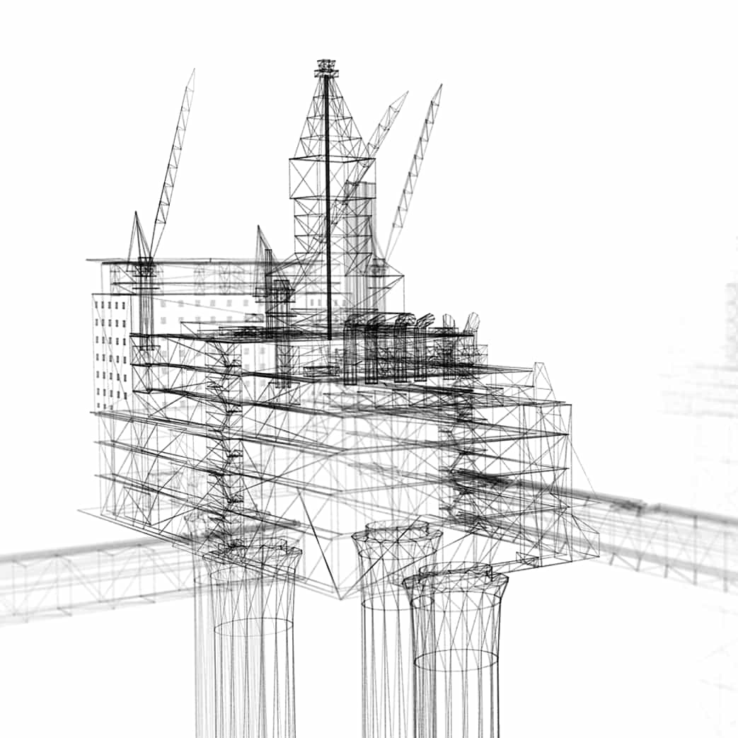
Scanned technical blueprint before AI processing
01 Technical Blueprint
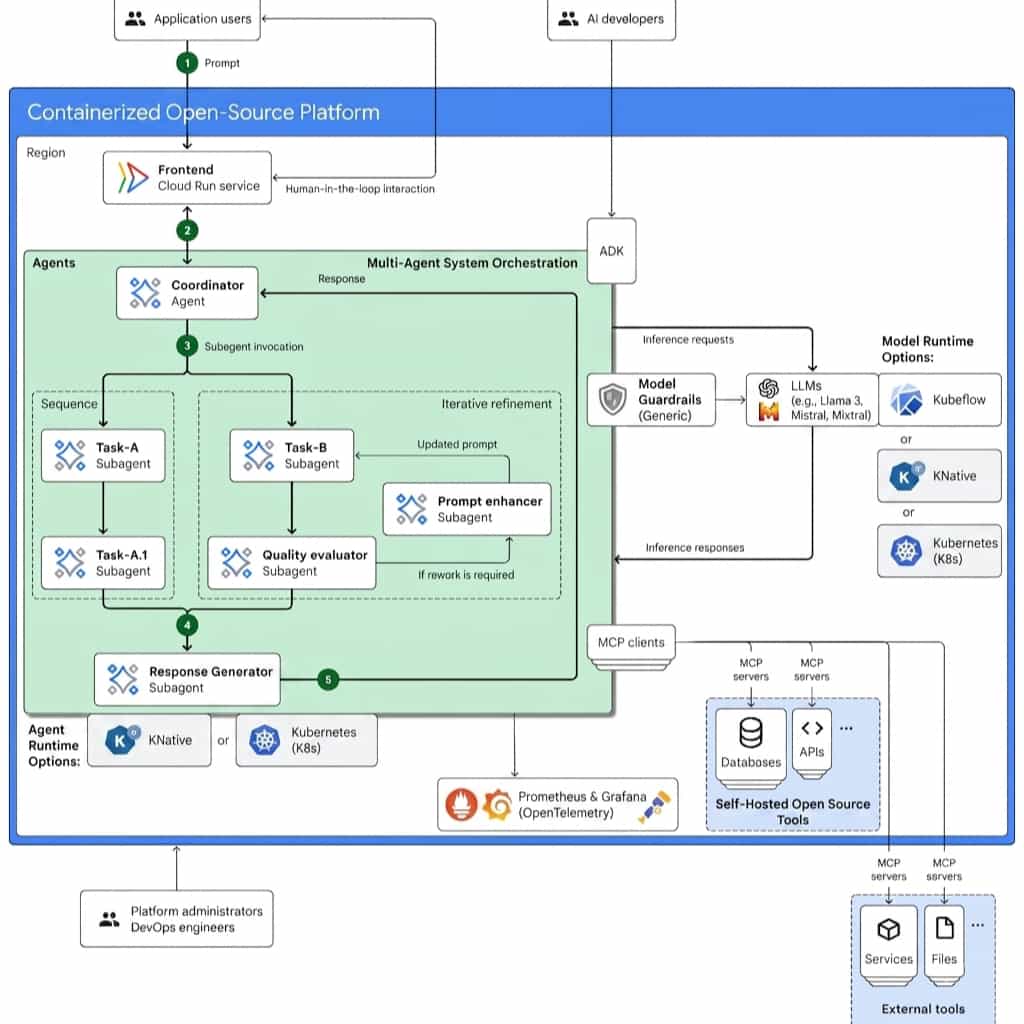
Specialist agent swarm analysing the drawing's knowledge graph
02 Multi Agentic AI
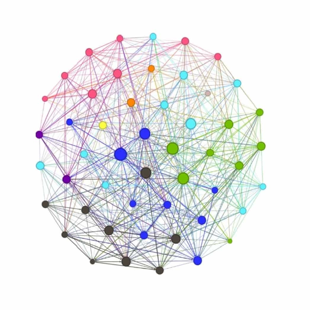
Drawing data structured into a knowledge graph
03 Knowledge Graph
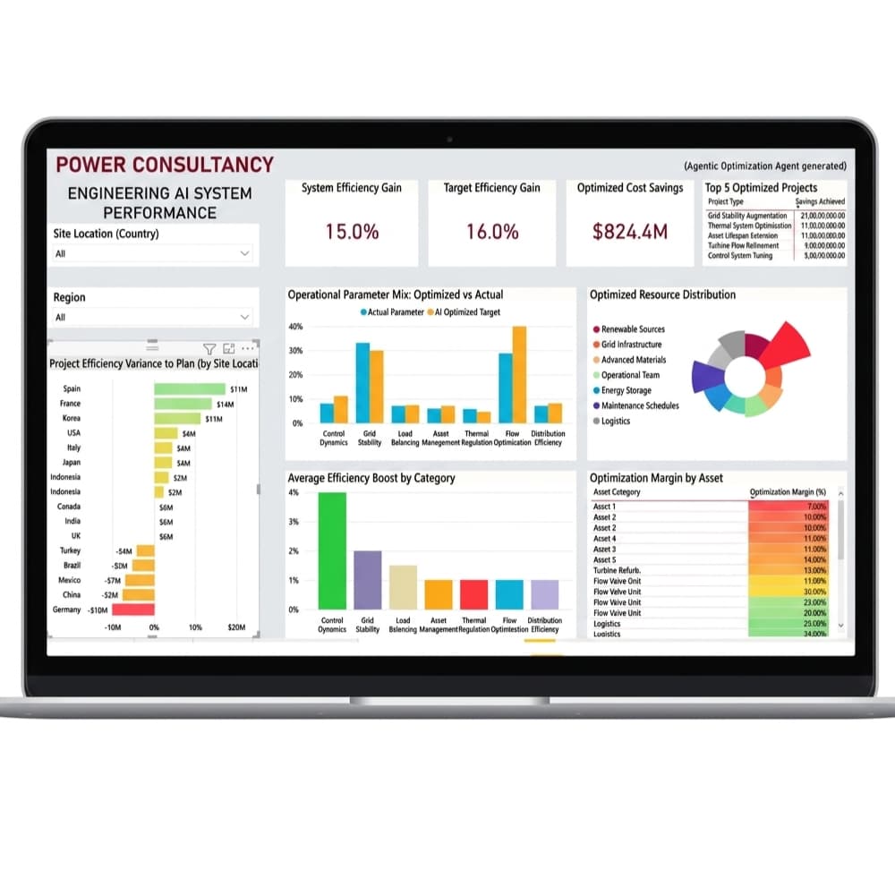
Findings surfaced in the solution dashboard for reviewer sign-off
04 Solution Dashboard

Blueprint

Every P&ID your engineers touch becomes a live knowledge graph : read, cross-checked against code, and redlined against your own standards before it ever reaches a human reviewer.

AI Architecture

Multi‑Agentic AI
On‑Premise · Zero External Calls (configurable) · SHA‑256 Sealed

Why Chatbot-Style AI
Cannot Do This Job

It is tempting to point a general-purpose language model at a folder of drawings and call it done. Here is what actually happens when you try.

Chunked retrieval
A feature control frame gets split from the datum reference it depends on because they sit on different sides of a text-chunk boundary. The model answers confidently about a tolerance with no idea what it is measured relative to.
Structural fix
We do not chunk the drawing. Every dimension, symbol, and note becomes a node in a knowledge graph, connected to its datums by typed, queryable relationships. Nothing can be separated from what it depends on.
Fluent guessing
Asked whether a callout meets ISO 2768, the model produces a plausible-sounding clause number. It does not exist. Nobody catches it until a supplier builds to a specification that was never real.
Structural fix
Every standard our system cites is a verified entry in a maintained clause library, not a generated string. If a clause cannot be matched, the system says so, out loud, instead of inventing one.
No arithmetic
A language model can describe what a tolerance stack-up is. It cannot reliably compute one. Worst-case and statistical stack-up are exact arithmetic problems, and approximate language generation is the wrong tool for exact arithmetic.
Structural fix
Dimension chains are extracted into a symbolic equation system and solved exactly, worst-case and root-sum-square both, using a computer algebra engine. The language model never touches the numbers.
Black box
The model says a drawing "looks fine." Nobody can ask which region it looked at, what threshold it used, or why it missed the same error a junior engineer catches on the first pass.
Structural fix
Every step is logged against the exact pixel region and graph node that produced it. A finding can always be traced backward to the specific line on the specific sheet that caused it.
Cloud dependency
The fastest way to try any of this is to upload your drawings to a third-party API. For export-controlled designs, defence programs, or unreleased product geometry, that is not a workflow, it is an incident.
Structural fix
The entire system runs inside your perimeter. Air-gapped operation is a supported mode, not a special request.

A Multi-Agent Cognitive Pipeline, Not a Single Model

Six stages, a shared blackboard (Redis for working state, Postgres for records, Neo4j for the knowledge graph), and a council that owns final judgment when agents disagree.

Ingest Parse Ground Unify Analyse Seal
01
Ingestion & Normalisation

Accepts scanned raster (PDF, TIFF, JPEG) and native CAD-derived vector formats without preference; a fortieth-generation photocopy and a fresh export from the CAD system go through the same pipeline. Deskew, contrast normalisation, and resolution targeting to 4096x4096 for legibility of small callouts.

Every sheet returns a per-region confidence score before anything downstream touches it. Sheets that fall below threshold are routed back for a re-scan request rather than silently processed at low fidelity. A wrong answer confidently stated is worse than no answer.

Raster + vectorConfidence gating
02
Layout & GD&T Semantic Parsing

A vision-language layout model segments the sheet into its real document structure: title block, bill of materials table, orthographic and section views, notes, revision block. This is document understanding, not object detection: the model has to know that a table inside a border is a BOM, not a note.

The layer that matters most sits underneath: every feature control frame is parsed into a structured object under ASME Y14.5 and the ISO GPS family (ISO 1101 for form and orientation, ISO 5459 for datum systems, ISO 8015 for the governing principle). A feature control frame is never treated as text. It is decomposed into its characteristic symbol, tolerance zone, material modifiers, and datum reference frame, each one a queryable field.

ASME Y14.5ISO 1101 / 5459 / 8015Structured FCF parsing
03
CAD Grounding & Model-Based Definition

The drawing number and revision are used to retrieve the authoritative 3D model from your PLM or CAD vault, exchanged as STEP AP242, the interchange format built specifically to carry model-based definition data including PMI (product manufacturing information) alongside geometry. The 2D sheet is registered against the 3D model through feature matching, so every view is understood as a projection of a specific, known solid rather than an image to be interpreted from scratch.

Where no CAD record exists, an older drawing with no digital twin, the system falls back to constrained 3D reconstruction from the orthographic views themselves, flagged at lower confidence and routed for human confirmation before anything downstream depends on it.

STEP AP242PMI-aware2D/3D registration
04
The Knowledge Graph

Every extracted fact becomes a node: Part, Feature, Dimension, Tolerance, Datum, Material, Process, Standard Clause, Revision. Edges are typed and directional: a Dimension constrained-by a Tolerance, a Tolerance referenced-to a Datum, a Datum defined-on a Feature, a Revision supersedes a prior Revision. This is what makes traceability a query rather than an act of faith.

Dimension: Ø42.5 H7constrained-by →Tolerance: position, 0.1mm, MMC
Tolerance: position, 0.1mm, MMCreferenced-to →Datum: A | B | C
Datum: Adefined-on →Feature: flange face, Sheet 2
Tolerance: position, 0.1mm, MMCgoverned-by →Clause: ASME Y14.5 §7.4
Neo4jTyped provenance edges
05
The Analysis Swarm

Specialist agents run against the graph, not the image. A tolerance stack-up analyser walks dimension chains and solves them symbolically, both worst-case and statistical. A manufacturability advisor checks callouts against the process capability of your actual production methods rather than generic textbook rules. A revision-delta agent diffs the current graph against the prior revision's graph, so a quietly moved datum shows up as a structural change, not a paragraph you have to notice.

Each agent returns not just a verdict but a formal reasoning trace: which nodes it read, which equation it solved, what the result was.

agent: tolerance_stackup_analyzer
chain: [D-042, D-044, D-051] → bolt_circle_position
datum_ref: A|B|C method: worst_case
computed: 0.133mm allowed: 0.100mm
result: EXCEEDS TOLERANCE by 0.033mm
delta_vs_rev_C: datum B relocated (Sheet 3, +0.4mm)
status: routed to conflict resolution council
Symbolic solverGraph diffFormal traces
06
Conflict Resolution & Sealing

When two agents disagree, a tolerance pass from one analysis method against a manufacturability fail from another, a resolution council applies weights specific to your organisation's risk tolerance, documents the dissent rather than silently picking a winner, and produces a single output.

That output is hashed with SHA-256 and written to an immutable audit ledger. The hash is not decoration. It means the finding you are looking at today is provably the finding the system produced at the time, unaltered, by anyone, including us.

Weighted councilSHA-256 sealedImmutable ledger

The Standards We Implement,
the Math We Solve

StandardWhat it governs, here
ASME Y14.5-2018Geometric dimensioning and tolerancing: feature control frames, datum reference frames, material condition modifiers.
ISO 1101Form, orientation, location, and run-out tolerancing for the ISO GPS system.
ISO 5459Datums and datum systems: how reference frames are established and combined.
ISO 8015The governing envelope principle underpinning every other GPS standard we implement.
AP242 (STEP)Model-based definition interchange: geometry plus PMI in one traceable file.
21 CFR Part 11Electronic record and signature integrity, applied where the medical device sector requires it.
Tolerance Stack-Up, Both Methods
Twc = Σ |Ti|
Trss = √(Σ Ti²)
Worst-case sums every contributing tolerance directly: the conservative bound nobody can dispute. Root-sum-square treats each contributor as statistically independent, giving a realistic bound for high-volume production. We compute both and let your process capability (Cpk) decide which one governs the pass/fail line.

Your Design IP Never Leaves Your Perimeter.

Proprietary drawings, 3D models, and manufacturing know-how are your most valuable assets. Vendor-hosted AI asks you to upload them to someone else's infrastructure. We do the opposite: the system deploys inside your environment, under keys you hold.

Inference
GPU nodes running the vision-language parser and unification models, inside your compute environment.
Graph Store
Neo4j holding the full part, tolerance, and standards ontology, queryable and exportable.
Object Store
Source sheets, 3D models, and sealed reports, encrypted under your key management, not ours.
PLM / CAD Bridge
Connectors to your existing systems. No data staging outside your network boundary.
Customer-Held Keys
All data encrypted under keys you control. We hold no decryption capability over your drawings or BOMs.
Air-Gap Capable
Full operation without internet connectivity, for defence, classified, and export-controlled work.
Model Updates, No Egress
Updates ship to you. Your drawings never ship to us for training or fine-tuning.
PLM Integration
Connectors available for Teamcenter, Windchill, SAP, Onshape, and SolidWorks PDM.